
ABRASIVE WHEEL GRINDER
Abrasive wheels and grinding machines come in many styles, sizes and designs. Bench and pedestal grinders are frequently used in machine shops. They usually have two abrasive wheels or one abrasive wheel and one special purpose wheel such as a wire brush.
These grinders create a number of safety issues. The rotating wheel can shatter. They come equipped with shielding that is strong enough to withstand the effects of a shattering wheel. The rotating wheel is a natural abrasive hazard to the fingers. In addition there are concerns related to flying fragments, sparks and air contaminants.
Abrasive wheels must be equipped with safety guards. The guard encloses most of the wheel. It covers the flange, the spindle, and nut projection. The exposed area of the wheel should not exceed 90 degrees of the periphery. The distance between the safety guard and the top periphery of the wheel must not exceed ¼ inch. An adjustable tool/work rest must be present and maintained at a maximum clearance of 1/8 inch between it and the face of the wheel. Plexi-glass shields are optional. They are not included in as part of the guard. All abrasive wheels must be inspected for cracks and defects prior to installation. The spindle speed of the grinder must be checked to make sure it doesn’t exceed the maximum operating speed marked on the wheel.
BAND SAW

Band saws used in metal working shops may be horizontal or vertical. Both operate in a similar manner and have similar inherent safety hazards.
A vertical band saw uses a thin flexible continuous steel strip with cutting teeth on one edge. The blade runs on two pulleys and through a work table where material is manually fed. In order to cut the metal the operator must hand fed and manipulate the stock against the blade. The operator must keep the stock flat on the work table and maintain the proper amount of force.
If the operator contacts the blade serious cuts or amputations can occur. The entire blade except at the point of operation should be guarded. An adjustable guard should be used for the portion of the blade above the sliding guide rods that raises and lowers with the guide. The blade guide should be as close as possible to the stock. The pulleys must be fully enclosed.
A horizontal band saw works in much the same manner as a vertical saw. The blade runs horizontally on two pulleys through two separate guides. The entire blade should be guarded except for the working portion of the blade which is between the two guides. Band saw wheels and pulleys must be enclosed.
CUT OFF SAWS
There are many specific types of cut off saws. They are all circular saws which cross cut stock at exact length and angles. Some of the most common are miter, chop, swing and jump saws. Severe cuts to the fingers, hands, or amputations can occur if they contact the saw blade. Overhead swing saws can pose additional hazards if the return device fails, if it bounces forward from a retracted position, or if the blade is able to go past the edge of the table.
Miter, chop and overhead swing saws must be provided with fixed hood guards that enclose the arbor and top half of the saw. These saws should be equipped with a self-adjusting lower blade guard that automatically adjusts to the thickness of the material being cut. Overhead saws shall be provided with a device to return the saw automatically to the back of the table when released at any point of its travel. They must also be limited to keep the saw from swinging beyond the front or back edges of the table. Under table swing saws and jump saws shall be guarded by their enclosure when idling. These saws must also have a guard affixed to the saw table in front of the hood guard to prevent accidental injury into the path of the saw blade from the front.
DRILL PRESS
The drill press is a machine that uses a multiple cutting-edged drill bit secured in a rotating chuck to bore and drill holes in stock. They are a standard item in machine shops. Serious injuries can occur if the operator contacts the rotating bit or chuck. Most injuries happen when the operator tries to hold the stock by hand when drilling. If not adequately secured the stock may spin violently.
Jigs should be used to stabilize the work piece. Holding the stock by hand should never be done. In repetitive drilling applications specially designed guards or shields may be used to protect the operator.
METAL WORKERS
Metalworkers are metal fabricating machines that offer tooling options to perform punching, shearing, notching, copying and bending operations. These machines are normally hydraulically operated. Crushing injuries or amputations can occur if the operator makes contact with any of the pinch or shear points present on the machine. Flying or ejected parts from either the stock or tooling can strike people present in the area. Unprotected foot pedals can also increase the potential of inadvertent cycling.
All pinch and shear points should be guarded. Guards should be adjustable down to ¼ inch from the top of the material to the bottom of the guard. Foot pedals should be covered to prevent accidental cycling. Make sure the punch and dies are properly aligned otherwise they may shatter and produce projectiles.
LATHE
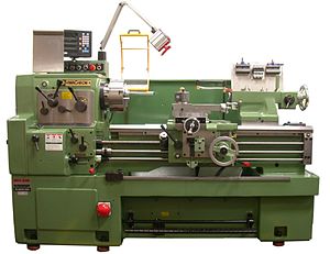
A metal lathe is a precision turning machine that rotates a metal rod or irregular shaped material while a tool cuts into the material at a preset position. The metal lathe normally consists of a headstock and base that houses one or more spindles on which a work holding device can drive the stock and the cutting tools can remove metal. Mainly cylindrical and conical shapes are produced on a lathe. There are two basic types of lathes; those fore shaft work and those for bar work. Shaft lathes include engine lathes, vertical shaft lathes and turning centers. Bar lathes include turret lathes and vertical boring mills.
Severe injuries can result from being caught in or struck by the rotating parts. An operator can be pulled into the lathe from walking too close or wearing gloves or loose clothing, hair or jewelry. Unsecured work pieces and flying chips can strike the operator or nearby people.
Gloves, loose clothing, long hair, jewelry or other dangling objects should not be worn around a lathe. Special attention should be given to work pieces that have keyway slots or other surface profiles that may increase the risk of entanglement. If rotating material must be manually polished use the emery cloth with the aid of a tool. A brush should be used to remove chips. Work holding devices and tool trapping space hazards should be covered with guards or shields. Vertical lathes and turning centers should be interlocked to prevent access during the automatic cycle. Make sure work pieces and work holding devices are free from defects. Never leave the chuck key in the lathe. A chip/coolant shield should be in place.
MILLING MACHINE
A milling machine removes material from a work piece by rotating a cutting tool and moving it into the work piece. Milling machines may be either vertical or horizontal. They can be used to drill, bore, and cut gears, threads and slots. The vertical mill is the most common found in machine shops today. Generally the mill includes the quill, the knee and the column. The quill moves vertically in the head and contains the spindle and cutting tools. The knee moves up and down by sliding parallel to the column. The column holds the turret which allows the milling head to be positioned above the table.
Serious injuries can result if the operator comes into contact with the rotating cutter. Metal shavings present a measure of risk. Injuries can also result from a wrench or other tools left in the spindle.
The work piece must be secured by clamping it to the work table or in a vice that is attached to the work table. A guard or shield that encloses the cutter head or milling bed should be present to protect the operator from the cutting area, metal shavings, and fluids.
CNC TURNING MACHINE
Computer numerically controlled (CNC) turning machines cut and shape an assortment of precision parts. They can operate in either horizontal or vertical positions. The functions formally performed by human operators are performed by a computer control module. CNC machinery may be hand loaded or automatically fed.
The two primary hazards arising from CNC turning operations are entanglement in or between the tooling or the rotating work piece and the injection of parts. Serious lacerations, fractures, amputations, and even death can result. The CNC enclosure is generally interlocked however this does not eliminate the risk of injury from ejected parts. Studies have shown that the polycarbonate materials generally used in the machines vision panels can degrade after exposure to the fluids and lubricants used in the machining process. Over time the vision panels may not be able to contain ejected parts.
To prevent access to the point of operation the CNC machine should be fully enclosed with an interlock guard on the doors. The cutting tools should not start if the doors are open and should stop if the doors are opened. The polycarbonate vision panels should be inspected regularly and replaced if damage or deterioration is present. In addition the required rotational speed for a particular work piece should be verified.
POWER PRESS
Power presses are metalworking machines need to cut, punch, or form metal using tooling dies. The two most common types of power presses are mechanically or hydraulically powered. The main components for power transmission on a mechanical press are the clutch, the flywheel, and crankshaft. The slide is attached to a crankshaft with connecting rods and the crankshaft is coupled to the flywheel, which is rotating when the motor is running. A clutch connects the spinning flywheel to the crankshaft. The crankshaft converts the rotary motion of the flywheel to the downward and upward motions of the press slide.
Two different types of clutches are used on mechanical power presses. Full revolution clutches, when tripped cannot be disengaged until the crankshaft has completed a full revolution and the press slide has completed a full stroke. Presses equipped with full revolution clutches are generally older models. A part-revolution clutch can be disengaged at any point before the crankshaft has completed a full revolution and the press slide has completed a full stroke.
Manually fed presses are cycled either by foot or by two handed controls. With foot controls the press is activated by pressing down on a foot switch or pedal. The hands are free during the cycling of the press. This freedom of hand movement places operators using foot controls at a greater risk of sustaining an injury at the point of operation. About twice as many injuries are from foot controlled presses. With two-handed controls, a work piece is positioned in the press and both hands must be removed from the point of operation to depress the buttons. The other major concern is safely in stalling, removing, and transferring the dies.
Crushing and amputations at the point of operation or while servicing dies are the most likely injuries to occur when operating power presses. About half of all injuries from power presses result in amputations. The number of amputations nationally is about 10,000 annually.
At the point of operation all presses must be safeguarded either by barrier guarding or the use of devices. Barrier guarding prevents entry into the die area by physically enclosing the point of operation. Devices control entry by allowing the operator to reach into the die are to fed or remove parts and will either prevent a machine cycle, stop the down stroke, or pull the operators hands out if his/her hands are detected or remain in the point of operation. Guarding is not required if the point of operation is ¼ inch or less.
Barrier guarding must be designed or constructed so that people cannot reach over, under, around or through the guard and reach the pitch point hazard. If there are openings in the barrier guard the openings must comply with the following standard.
Barrier Guard Standard for Opening Sizes
| Distance of opening from point of operation hazard (in.) | Maximum width of opening (in.) |
|---|---|
| ½- 1 ½ | ¼ |
| 1 ½ – 2 ½ | 3/8 |
| 2 ½ – 3 ½ | 1/2 |
| 3 ½ – 5 ½ | 5/8 |
| 5 ½ – 6 ½ | 3/4 |
| 6 ½ – 7 ½ | 7/8 |
| 7 ½ – 12 ½ | 1 1/4 |
| 12 ½ – 15 ½ | 1 1/2 |
| 15 ½ – 17 ½ | 1 7/8 |
| 17 ½ – 31 ½ | 2 1/8 |
POWER PRESS BRAKE
These machines bend and form parts through the use of tooling dies attached to a ram. Metal working occurs by placing a stock on a bottom die and pressing it with a top die attached to the moveable ram. Press brakes are mechanically or hydraulically powered or both. Mechanical press brakes are either mechanical friction or air friction clutches that can be disengaged at any point before the crankshaft has completed a full revolution and the press slide has completed a full stroke. By slipping the clutch the operator may drop the slide to the work piece and stop, adjust, or align the work piece then complete the stroke. Hydraulic press brake can normally be stopped at any point in their cycle and the force exerted by the dies can be varied. Regardless of how the press is powered the basic operation involves the operator finding or placing the stock on the bottom die. Positioning the stock properly and activating the press cycle with hand or foot controls. One important difference in mechanical and hydraulic brakes is there is no way to reverse the stroke on mechanical brakes. Although it can be stopped or inched the stroke must be completed.
Since the press brake can bend metal with ease it is obvious that serious injuries can result. Although the operation of the press brake doesn’t require the operator to place his/her hands into the point of operation the proximity to the closing dies creates a significant risk. In addition the stock can sometimes bend upward rapidly creating a pinch point hazard and possibly striking the operator.
Installing and removing tooling provides the most direct hazard exposure as the operator must place his/her hands between the two dies. Hands or arms can be severely injured.
Press brakes are difficult to guard due to the flexibility needed to fabricate metal. Feasible safeguarding methods include presence sensing devices and two handed controls. These can normally be used without reducing productivity. A presence sensing device prevents the machine from cycling when the sensing field is obstructed prior to cycle initiation and stops the down stroke when the sensing field is obstructed after cycle initiation. Two hand controls are designed to keep the operators hands away from the die area by requiring concurrent and constant pressure ti cycle the machine. Both presence sensing devices and to hand controls must be located at a proper distance from the hazard so that the hazardous motion is stopped or prevented before the operator can enter the point of operation.
Prior to installing footing the ram should be locked in the shut height position with the ram in its most extended position on the upstroke. Once the press is locked into that position the footing can slide safely into the press. The gap between the ram and bed should be just big enough to allow easy installation without the footing falling out. Use safety blocks whenever possible. To prevent accidental cycling all hand and foot controls must be cycled.
A no hands in die policy except during set up should be strictly enforced. During set up effective die setting procedures and energy control methods must be used and will address the potential hazards.
POWER ROLL FORMING AND BENDING MACHINE
Conventional metal forming and bending machines produce smooth, circular bends in sheet, strip, and coiled stock. Metal is fed between successive pairs of rolls that progressively bend and form it until the desired shape and cross section is obtained. The radius of the bend is adjusted by changing the location of the rolls.
Severe injuries can occur if a person is caught and drown into the counter rotating infeed rolls. The risk of injury is highest during the initial feeding of the stock. Loose clothing, hair, and gloves with fingers increase the risk of entanglement. Workers can also be struck by a moving work piece or pinned between it and a fixed structure.
Installing barrier grinding at the point of operation is generally not practical. However these are some safety devices which reduce the hazard potential. Hold down buttons or foot controls are designed to actuate roll movement only when held in the run position. The control should be automatically return to the stop position when released. A trip device is effective. It is interlocked with the machine’s control circuit and positioned so it may be easily actuated by any person drawn toward the rolls and will stop the machine before serious injury can occur. It should run the entire length of the machine at the front and in the back. The braking system must be verified that it can stop the dangerous parts of the machine quickly. An emergency stop button should be provided at the machine control console and at any remote work station. Whenever practical feed or roller tables should be used.
SHEAR
Power shears and plate shears cut sheets of metal using either mechanical or hydraulic driven rams for shearing action. The ram moves a non-rotary blade at a constant rate past the edge of a fixed blade. The operator places stock between the blades, ensures it is properly positioned, and activates the cutting cycle with either foot or hand controls. The material hold down devices clamps the stock immediately prior to the shearing action.

The primary hazard at the point of operation is the shear action. Since blades are used the hazard to hands or fingers is severe. The hold down mechanism can create a very serious pinch point. Serious cuts can also occur when handling the blades.
Shear blades are normally guarded by a barrier capable of adjusting to the thickness of the stock. An adjustable barrier guard must be provided in front of the hold down devices to protect the operator. They must be adjustable so the operator can feed the stock but cannot get their hands or fingers into the hazard zone. On mechanical shears equipped with a part-revolution clutch or for those that are hydraulically powered, presence sensing devices or two hand control devices should be utilized. Gloves may be worn when handling stock. Special care should be taken when removing, handling and installing the blades. Hand and foot controls should be enclosed or shrouded to eliminate accidental cycling. The back of the shear, where the debris drops, should be barricaded.